Blogger Tips and TricksLatest Tips And TricksBlogger Tricks
Showing posts with label Electronics & Communication. Show all posts

Tuesday, 2 August 2016

Scilab

Scilab is free and open source software for numerical computation providing a powerful computing environment for engineering and scientific applications.
Scilab is released as open source under the CeCILL license (GPL compatible), and is available for download free of charge. Scilab is available under GNU/Linux, Mac OS X and Windows XP/Vista/7/8 (see system requirements).

What is Scilab ?
Scilab includes hundreds of mathematical functions. It has a high level programming language allowing access to advanced data structures, 2-D and 3-D graphical functions.
A large number of functionalities is included in Scilab:

EAGLE PCB Desing

Schematic Editor
The goal of the schematic is to provide documentation about the design, allowing others to easily understand your design intent. EAGLE comes with thousands of pre-made parts that simplify your schematic capture tasks.
Layout Editor
You can locate your components accurately and route copper traces between them. EAGLE's Layout editor includes sophisticated features such as assembly variants, differential pair routing and much more.
Autorouter
The autorouter can be guided by adjusting its cost factors to control its routing behavior producing useful results in no time. The Autorouter protects prerouted traces giving you full control over what nets need to be manually routed and which can be routed automatically.
Download

KiCAD

A full Getting Started guide is included in the KiCad documentation, in multiple languages. This covers the process of creating and completing a simple project. We recommend that all new users read this first, in order to learn the basics.

Quick KiCad Summary
This is a quick summary of how KiCad functions. More details can be found in the full documentation.

Libraries
KiCad uses two separate types of library: symbols (.lib) and footprints (.pretty). Symbols are used to draw the schematic. Once symbols have been placed into the schematic, footprints are assigned to them, and then these are used to lay out the circuit board.

Saturday, 26 March 2016

BRL-CAD

BRL-CAD is a powerful open source cross-platform solid modeling system that includes interactive geometry editing, high-performance ray-tracing for rendering and geometric analysis, a system performance analysis benchmark suite, geometry libraries for application developers, and more than 30 years of active development.

BRL-CAD is a powerful cross-platform Open Source combinatorial Constructive Solid Geometry (CSG) solid modeling system that includes interactive 3D solid geometry editing, high-performance ray-tracing support for rendering and geometric analysis, network-distributed framebuffer support, image and signal-processing tools, path-tracing and photon mapping support for realistic image synthesis, a system performance analysis benchmark suite, an embedded scripting interface, and libraries for robust high-performance geometric representation and analysis.

A9CAD

A general purpose 2-dimensional CAD program. It supports industry standard DWG/DXF drawing formats. With A9CAD you can draw shapes such as line, rectangle, circle, poly-line, text and dimension; performing drawing modifications like move, scale, rotate, explode, trim, fillet and mirror; edit color, fill mode, line type and line width; change entity attributes via properties window. Manage drawing styles and settings and configure drawing environments.

Geomagic Design

Driving Engineering Forward with Geomagic Design
With comprehensive 3D CAD tools for design, engineering and preparation for manufacturing, Geomagic Design empowers rapid, accurate product development in an easy-to-use environment.

At a highly affordable price point, Geomagic Design delivers top-end tools at lower cost, including comprehensive assembly, parametric and direct editing tools, 2D documentation, sheet metal design, motion analysis and integrated CAD data sharing tools.

Thursday, 10 March 2016

GLE - Graphics Layout Engine

Description
GLE is a graphics scripting language designed for creating publication quality graphs, plots, diagrams, figures and slides. GLE relies on LaTeX for text output. Its output formats include EPS, PS, PDF, JPEG, and PNG. GLE (Graphics Layout Engine) is a graphics scripting language designed for creating publication quality figures (e.g., a chart, plot, graph, or diagram). It supports various chart types (including function plot, histogram, bar chart, scatter plot, contour plot, color map, and surface plot) through a simple but flexible set of graphing commands. More complex output can be created by relying on GLE's scripting language, which is full featured with subroutines, variables, and logic control. GLE relies on LaTeX for text output and supports mathematical formulae in graphs and figures. GLE's output formats include EPS, PS, PDF, JPEG, and PNG. GLE is licenced under the BSD license. QGLE, the GLE user interface, is licenced under the GPL license.

Categories
Graphics, Visualization

License
BSD License

FormScanner - Free OMR Software

Description
FormScanner is an OMR (Optical Mark Recognition) software that automatically marks multiple-choice papers.
FormScanner not bind you to use a default template of the form, but gives you the ability to use a custom template created from a simple scan of a blank form.
The modules can be scanned as images with a simple scanner and processed with FormScanner software.
All the collected information can be easily exported to a spreadsheet.

Categories
Information Analysis

License
GNU General Public License version 3.0 (GPLv3)

Asymptote

2D & 3D TeX-Aware Vector Graphics Language
Description
Asymptote is a powerful descriptive vector graphics language for technical drawing, inspired by MetaPost but with an improved C++-like syntax. Asymptote provides for figures the same high-quality typesetting that LaTeX does for scientific text.

Features of Asymptote:


  • provides a portable standard for typesetting mathematical figures, just as TeX/LaTeX has become the standard for typesetting equations;


  • generates high-quality PostScript, PDF, SVG, or 3D PRC vector graphics;


  • embeds 3D vector PRC graphics within PDF files;


  • inspired by MetaPost, with a much cleaner, powerful C++-like programming syntax and IEEE floating-point numerics;


  • runs on all major platforms (UNIX, MacOS, Microsoft Windows);


  • mathematically oriented (e.g. rotation of vectors by complex multiplication);


  • LaTeX typesetting of labels (for document consistency);


  • uses simplex method and deferred drawing to solve overall size constraint issues between fixed-sized objects (labels and arrowheads) and objects that should scale with figure size;


  • fully generalizes MetaPost path construction algorithms to three dimensions;


  • compiles commands into virtual machine code for speed without sacrificing portability;


  • high-level graphics commands are implemented in the Asymptote language itself, allowing them to be easily tailored to specific applications.
  • NetToPLCSim

    Overview
    NetToPLCSim extends the Siemens PLC Simulation Software "PLCSIM" by a TCP/IP network interface for variable services, so you can test your HMI/SCADA-Software together with PLCSIM without real hardware.

    Version information
    There are two versions of NetToPLCSim which are using a different interface to exchange data with

    PLCSim:
    S7online-Version. All versions since V0.9.x.
    S7ProSim-Version. All versions V0.7.x and before It's recommended to use the S7online-Version.

    Saturday, 5 March 2016

    Logic Gate Simulator

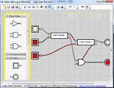
    Logic Gate Simulator is an open-source tool for experimenting with and learning about logic gates. The simulator tool was originally designed for CIS students at South Puget Sound Community College but is free for anyone to use and modify under the GPL v3.

    Logic Gate Simulator is written in C#/WPF using .NET 4
    Watch a 3 minute video demonstration
    Dave Jordan has implemented a multiplier, download am.gcg

    Selected Features

    1. Graph circuit activity over time
    2. Drag-and-drop gate layout and wiring
    3. User created "integrated circuits" for re-use
    4. Viewing the activity inside ICs during simulation
    5. Adjustable simulation speed and zoom
    6. Print and export as image
    7. Cut/copy/paste
    8. Inline ICs and flatten entire circuits


    GHDL - a VHDL simulator

    Description
    GHDL is the leading open source VHDL simulator.

    We have binary distributions for Debian Linux, Mac OSX and Windows. On other systems, getting GHDL from here means downloading the current source package and building GHDL from source. Alternatively you can get the latest source version (warning : occasionally unstable!) by pulling a snapshot from the git repository.

    Categories
    Electronic Design Automation (EDA)

    License
    GNU General Public License version 2.0 (GPLv2)

    Download

    PICsim - PIC microcontroller simulator

    Description
    PICsim emulates a microcontroller PIC16F628/16F777/16F877A/18F452/18F4550/18F4620 and periferics such as USART and timers, the simulator architecture permit easy implementation of external elements in c language. PicsimLab is a realtime emulator of development boards with integrated MPLABX debugger.
    Categories
    Testing, Simulations, Electronic Design Automation (EDA), Computer Aided Instruction (CAI)
    License
    GNU General Public License version 2.0 (GPLv2)

    CEDAR Logic Simulator

    CEDAR LS is an interactive digital logic simulator to be used in the teaching of digital logic design classes, or for testing simple digital designs. CEDAR Logic Simulator features both low-level logic objects, as well as some register-level functions. Features * Drag-and-drop interface o Gates are dragged from a categorized palette onto a tabbed circuit canvas o Wire connections are made by dragging from one connection point to another' * Interactive wiring system o Continuing simulation shows color-coded wires for 5-state logic o Wires rubber-band when connected gates are moved o Wire segments may be dragged to fit circuit design * Circuit time-step control o Simulation may be continuous with a user-specified time per step o Play/Pause control * User-friendly circuit navigation o Keyboard scrolling o Miniature map display for large circuits o Zoom in/out control o Group select o Copy/Paste for wires, gates, and selected groups o Circuits on different tabs may be connected with named bridge gates o Print and Export to Bitmap functions

    Categories
    Simulations, Visualization

    License
    BSD License

    Advanced HMI

    Manufacturing Automation is a software development company that specializes in software for automation and manufacturing.


    AdvancedHMI is our most popular off-the-shelf packages. It is used to build HMI applications for machinery or facility control. It has several advantages over other HMI software and hardware. These include unlimited flexibility, extend-ability, and cost. The base package is absolutely free and unrestricted, so give it a try for yourself.

    Features

    • Allen Bradley DF1 RS232 Driver
    • Allen Bradley Ethernet/IP Driver for SLC,MicroLogix, ControlLogix, and CompactLogix
    • Beckhof TwinCAT Driver, ModbusTCP and ModbusRTU drivers
    • Omron Drivers
    • Drivers are accessible via VB or C# code
    • Build an HMI in Visual Studio 2010-2013 (free) without writing any code
    • Works with Visual Studio Community Edition
    • Tested on Mono on Linux (except OPC driver)
    • Even Works on the Raspberry Pi

    ngspice

    Ngspice is a mixed-level/mixed-signal circuit simulator. Its code is based on three open source software packages: Spice3f5, Cider1b1 and Xspice. It is the open source successor of these venerable packages. Many, many modifications, bug fixes and improvements have been added to the code, yielding a stable and reliable simulator. Therefore, besides being used as a standalone simulator, Ngspice has been incorporated into many projects, see our simulation environments page.

    Spice3 does not need any introduction, is the most popular circuit simulator. In over 30 years of its life Spice3 has become a de-facto standard for simulating circuits.

    Cider couples Spice3f5 circuit level simulator to DSIM device simulator to provide greater simulation accuracy of critical devices. DSIM devices are described in terms of their structures and materials.

    Thursday, 3 March 2016

    Arduino- Software

    The open-source Arduino Software (IDE) makes it easy to write code and upload it to the board. It runs on Windows, Mac OS X, and Linux. The environment is written in Java and based on Processing and other open-source software.
    This software can be used with any Arduino board.
    Refer to the Getting Started page for Installation instructions.

    Wednesday, 2 March 2016

    QUCS : A circuit simulator with graphical user interface (GUI)

    Qucs stands for Quite Universal Circuit Simulator. So far Qucs is not yet finished, but it is already packed with features. Take a look at the screenshots to get a feel for what it can do. Qucs is an integrated circuit simulator which means you are able to setup a circuit with a graphical user interface (GUI) and simulate the large-signal, small-signal and noise behaviour of the circuit. After that simulation has finished you can view the simulation results on a presentation page or window. Qucs, briefly for Quite Universal Circuit Simulator, is a circuit simulator with graphical user interface (GUI). The GUI is based on Qt® by Digia®. The software aims to support all kinds of circuit simulation types, e.g. DC, AC, S-parameter, Harmonic Balance analysis, noise analysis, etc.
    Qucsator, the simulation backend, is a command line circuit simulator. It takes a network list in a certain format as input and outputs a Qucs dataset. It has been programmed for usage in the Qucs project but may also be used by other applications.
    The Qucs GUI is well advanced and allows setting up schematics and presenting simulation results in various types of diagrams. DC, AC, S-parameter, noise and transient analysis is possible, mathematical equations and use of a subcircuit hierarchy (with parameterised subcircuits) are available. Qucs can also import existing SPICE models for use in your simulations.

    While Qucs is well developed, we still strive to improve the project, and will always welcome offers of help. Qucs doesn't just need help with programming, it also needs graphics, high quality example schematics, tutorials for the website and lots more.

    Qucs comes with a huge array of components and models including HICUM, BSIM2, BSIM3, and soon BSIM6. It also provides many semiconductor based components and models such as OpAmps, Diodes, MOSFETs, PMOSFETs and many more. Some example schematics can be found here which demonstrate some of the abilities of Qucs, and many more examples are provided with the program.
    Operating Systems

    Qucs is currently developed under the GNU/Linux OS using the standard autotools with no special effort to support other operating systems. However Qucs is said to be successfully compiled and run on Windows, Solaris, NetBSD, FreeBSD, MacOS, and Cygwin... help is needed !

    Logisim

    Description
    An educational tool for designing and simulating digital logic circuits, featuring a simple-to-learn interface, hierarchical circuits, wire bundles, and a large component library. As a Java application, it can run on many platforms.

    Logisim is an educational tool for designing and simulating digital logic circuits. With its simple toolbar interface and simulation of circuits as you build them, it is simple enough to facilitate learning the most basic concepts related to logic circuits. With the capacity to build larger circuits from smaller subcircuits, and to draw bundles of wires with a single mouse drag, Logisim can be used (and is used) to design and simulate entire CPUs for educational purposes.

    Logisim is used by students at colleges and universities around the world in many types of classes, ranging from a brief unit on logic in general-education computer science surveys, to computer organization courses, to full-semester courses on computer architecture.

    Description
    LibreCAD is a fully comprehensive 2D CAD application that you can download and install for free. There is a large base of satisfied LibreCAD users worldwide, and it is available in more than 20 languages and for all major operating systems, including Microsoft Windows, Mac OS X and Linux, including Debian, Ubuntu, Fedora, Mandriva, Suse, etc.
    LibreCAD is a free Open Source CAD application for Windows, Apple and Linux. Support and documentation is free from our large, dedicated community of users, contributors and developers. You, too, can also get involved!